Reference
This section describes the API in more detail.
Input Structs
The rotor object is defined as follows.
CCBlade.Rotor — TypeRotor(Rhub, Rtip, B; precone=0.0, turbine=false,
mach=nothing, re=nothing, rotation=nothing, tip=PrandtlTipHub())Parameters defining the rotor (apply to all sections).
Arguments
Rhub::Float64: hub radius (along blade length)Rtip::Float64: tip radius (along blade length)B::Int64: number of bladesprecone::Float64: precone angleturbine::Bool: true if using wind turbine conventionsmach::MachCorrection: correction method for Mach numberre::ReCorrection: correction method for Reynolds numberrotation::RotationCorrection: correction method for blade rotationtip::TipCorrection: correction method for hub/tip loss
The precone angle is shown below (commonly used with wind turbines, less so with propellers).
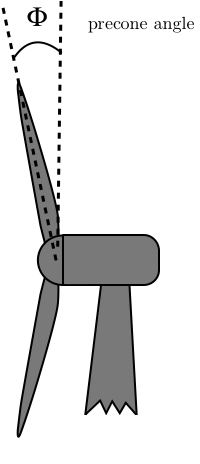
If there is precone then the Rhub and Rtip dimensions correspond to the length along the blade (instead of the radius from the center of rotation). That way when precone is changed, the blade just rotates instead of shearing as is more common. The turbine parameter is used for wind turbines, as discussed in Wind Turbine Operation. The remaining options are for airfoil (and tip loss) corrections and are discussed in Airfoil (and Tip) Corrections.
The Section object is defined as follows:
CCBlade.Section — TypeSection(r, chord, theta, af)Define sectional properties for one station along rotor
Arguments
r::Float64: radial location along bladechord::Float64: corresponding local chord lengththeta::Float64: corresponding twist angle (radians)af::Function or AFType: if function form is:cl, cd = af(alpha, Re, Mach)
Radius, like the hub and tip radii, follows along the blade. Note that we usually only specify interior r points (e.g., strict inequalities for Rhub < r < Rtip). However, CCBlade will allow you to specify points all the way to r = Rtip and/or r = Rhub, but because the loads are always zero at the hub/tip, the computation is bypassed for efficiency. The thrust/torque integration always extrapolates to zero loads at the tip so there is no benefit to including the ends, however there is no harm either.
Positive twist is shown below.
Airfoils are either a function as noted in the docstring, or a subtype of AFType, which in discussed in more detail in Airfoil Evaluation.
The remaining input is the operating point:
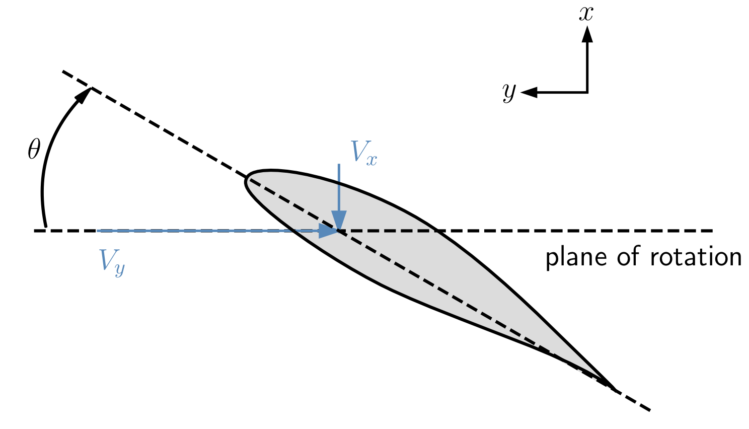
CCBlade.OperatingPoint — TypeOperatingPoint(Vx, Vy, rho; pitch=0.0, mu=1.0, asound=1.0)Operation point for a rotor. The x direction is the axial direction, and y direction is the tangential direction in the rotor plane. See Documentation for more detail on coordinate systems. Vx and Vy vary radially at same locations as r in the rotor definition.
Arguments
Vx::Float64: velocity in x-direction along bladeVy::Float64: velocity in y-direction along bladepitch::Float64: pitch angle (radians)rho::Float64: fluid densitymu::Float64: fluid dynamic viscosity (unused if Re not included in airfoil data)asound::Float64: fluid speed of sound (unused if Mach not included in airfoil data)
The inflow velocities $V_x$ and $V_y$ are seen in the figure above. This allows to user to specify a completely general input, but usually these aren't specified directly. Rather convenience functions are used to define these velocities across the blade (discussed below). Dynamic viscosity is only need if the airfoil data contains multiple Reynolds number. The speed of sound is only needed if the airfoil data contains multiple Mach numbers. Pitch twists the entire blade in the same positive direction as twist.
A simple propeller would have $V_x = V_\infty$ and $V_y = \Omega r$. That's essentially what the simple_op convenence function provides (with the addition of accounting for precone).
CCBlade.simple_op — Functionsimple_op(Vinf, Omega, r, rho; pitch=0.0, mu=1.0, asound=1.0, precone=0.0)Uniform inflow through rotor. Returns an OperatingPoint object.
Arguments
Vinf::Float: freestream speed (m/s)Omega::Float: rotation speed (rad/s)r::Float: radial location where inflow is computed (m)rho::Float: air density (kg/m^3)pitch::Float: pitch angle (rad)mu::Float: air viscosity (Pa * s)asounnd::Float: air speed of sound (m/s)precone::Float: precone angle (rad)
For wind turbines, a convenience function is provided windturbine_op that also includes yaw, tilt, azimuth, hub height, and a shear exponent.
CCBlade.windturbine_op — Functionwindturbine_op(Vhub, Omega, pitch, r, precone, yaw, tilt, azimuth, hubHt, shearExp, rho, mu=1.0, asound=1.0)Compute relative wind velocity components along blade accounting for inflow conditions and orientation of turbine. See Documentation for angle definitions.
Arguments
Vhub::Float64: freestream speed at hub (m/s)Omega::Float64: rotation speed (rad/s)pitch::Float64: pitch angle (rad)r::Float64: radial location where inflow is computed (m)precone::Float64: precone angle (rad)yaw::Float64: yaw angle (rad)tilt::Float64: tilt angle (rad)azimuth::Float64: azimuth angle to evaluate at (rad)hubHt::Float64: hub height (m) - used for shearshearExp::Float64: power law shear exponentrho::Float64: air density (kg/m^3)mu::Float64: air viscosity (Pa * s)asound::Float64: air speed of sound (m/s)
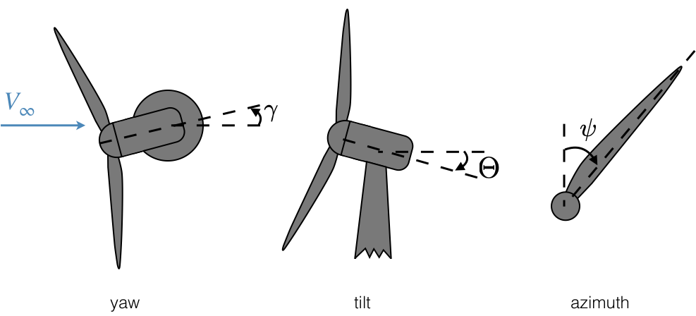
To account for the velocity change across the hub face we compute the height of each blade location relative to the hub using coordinate transformations (where $\Phi$ is the precone angle):
\[ z_h = r \cos\Phi \cos\psi \cos\Theta + r \sin\Phi\sin\Theta\]
then apply the shear exponent ($\alpha$):
\[ V_{shear} = V_{hub} \left(1 + \frac{z_h}{H_{hub}} \right)^\alpha\]
where $H_{hub}$ is the hub height. Finally, we can compute the x- and y-components of velocity with additional coordinate transformations:
\[\begin{aligned} V_x &= V_{shear} ((\cos \gamma \sin \Theta \cos \psi + \sin \gamma \sin \psi)\sin \Phi + \cos \gamma \cos \Theta \cos \Phi)\\ V_y &= V_{shear} (\cos \gamma \sin \Theta\sin \psi - \sin \gamma \cos \psi) + \Omega r \cos\Phi \end{aligned}\]
Output Struct
The full list of Outputs is as follows:
CCBlade.Outputs — TypeOutputs(Np, Tp, a, ap, u, v, phi, alpha, W, cl, cd, cn, ct, F, G)Outputs from the BEM solver along the radius.
Arguments
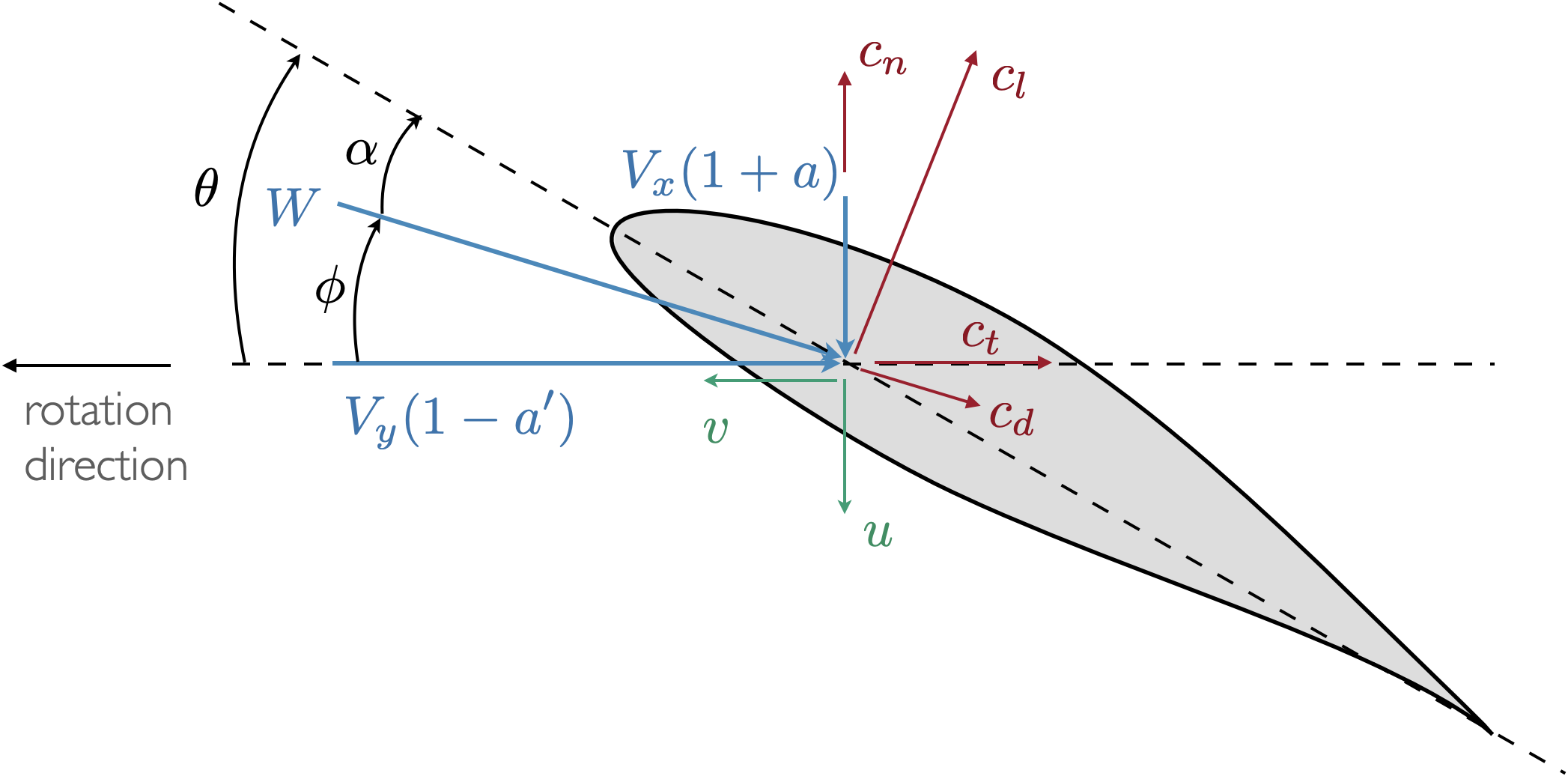
Np::Float64: normal force per unit lengthTp::Float64: tangential force per unit lengtha::Float64: axial induction factorap::Float64: tangential induction factoru::Float64: axial induced velocityv::Float64: tangential induced velocityphi::Float64: inflow anglealpha::Float64: angle of attackW::Float64: inflow velocitycl::Float64: lift coefficientcd::Float64: drag coefficientcn::Float64: normal force coefficientct::Float64: tangential force coefficientF::Float64: hub/tip loss correctionG::Float64: effective hub/tip loss correction for induced velocities:u = Vx * a * G, v = Vy * ap * G
Most of these parameters are defined in the figure below. The variables Np and Tp (where p is short for prime, as in a force per unit length) are in the cn and ct directions respectively.
When using broadcasting to retrieve multiple outputs at once (as would be commonly done for multiple sections along a blade) the return type is a StructArray from the StructArrays.jl package. A StructArray acts like a normal Array when indexed with integers, but can also be indexed with the output names like Np and Tp. To show this, we'll create an example Output array of length 4 with random data:
using CCBlade

# Create an array of `N` Outputs
N = 4
outs = Outputs.(rand(N), rand(N), rand(N), rand(N), rand(N), rand(N), rand(N), rand(N), rand(N), rand(N), rand(N), rand(N), rand(N), rand(N), rand(N))
4-element StructArray(::Vector{Float64}, ::Vector{Float64}, ::Vector{Float64}, ::Vector{Float64}, ::Vector{Float64}, ::Vector{Float64}, ::Vector{Float64}, ::Vector{Float64}, ::Vector{Float64}, ::Vector{Float64}, ::Vector{Float64}, ::Vector{Float64}, ::Vector{Float64}, ::Vector{Float64}, ::Vector{Float64}) with eltype Outputs{Float64}:
Outputs{Float64}(0.879085820993037, 0.8123814425714739, 0.3176894524912198, 0.922539103199775, 0.44141937953097554, 0.5339617506022242, 0.5153407884598117, 0.8568028082075354, 0.04153065525193789, 0.15582395764616963, 0.47177334267628046, 0.3912080838806983, 0.8736535572264261, 0.7946717273370788, 0.4235330420785246)
Outputs{Float64}(0.18399687069552095, 0.049122065769809264, 0.37053893302806784, 0.32857439689210344, 0.13028793921621296, 0.5373168692300319, 0.05905349903456114, 0.6694365973286885, 0.4578639369591466, 0.36912558896040715, 0.3580748770136706, 0.05830047053037146, 0.7056586824542679, 0.641797413629067, 0.36319826646792697)
Outputs{Float64}(0.09758427716739881, 0.7559738329924471, 0.4111789721740743, 0.766265329418779, 0.8104290630335327, 0.22568618712820276, 0.8005785143542032, 0.2861248759242342, 0.40377133132575405, 0.2767501174923066, 0.9177452690055932, 0.7570103457561529, 0.47273446227992744, 0.7846313364271423, 0.8027790704914135)
Outputs{Float64}(0.053147365129324387, 0.3653254303961656, 0.32852279489535474, 0.7478003874680211, 0.8870155118700743, 0.9658671625668147, 0.4802234071417695, 0.6789768957924601, 0.24778187688653996, 0.053132677085872215, 0.20557752519010863, 0.27317316992547946, 0.6514167819265838, 0.7511155510766284, 0.41497856702654967)Now we can retrieve all of the inputs for e.g. the third entry by indexing with an integer:
outs[3]Outputs{Float64}(0.09758427716739881, 0.7559738329924471, 0.4111789721740743, 0.766265329418779, 0.8104290630335327, 0.22568618712820276, 0.8005785143542032, 0.2861248759242342, 0.40377133132575405, 0.2767501174923066, 0.9177452690055932, 0.7570103457561529, 0.47273446227992744, 0.7846313364271423, 0.8027790704914135)But we can also get all of the e.g. Np outputs using outs.Np:
outs.Np4-element Vector{Float64}:
0.879085820993037
0.18399687069552095
0.09758427716739881
0.053147365129324387This was shown in the introductory tutorial. The same is true for the Section and OperatingPoint structs.
One subtle notes regarding the way the tip-loss factor works. The BEM methodology applies hub/tip losses to the loads rather than to the velocities. This is the most common way to implement a BEM, but it means that the raw velocities may be misleading as they do not contain any hub/tip loss corrections. To fix this we compute the effective hub/tip losses that would produce the same thrust/torque. In other words: $C_T = 4 a (1 + a) F = 4 a G (1 + a G)$ We solve this for G, and multiply it against the returned wake velocities $u$ and $v$ (but not the induction factors). Doing so allows us to return consistent values for the wake velocities, which may be of interest when computing interactions between rotor wakes and other objects.
Solve
Solve is the main function that takes in the three input structs (Rotor, Section, OperatingPoint) and returns the output struct (Outputs). Often broadcasting is used to call this function at multiple sections, or multiple sections and multiple operating points.
CCBlade.solve — Functionsolve(rotor, section, op; npts=10, forcebackwardsearch=false, epsilon_everywhere=false)Solve the BEM equations for given rotor geometry and operating point.
Arguments
rotor::Rotor: rotor propertiessection::Section: section propertiesop::OperatingPoint: operating pointnpts::Int = 10: number of discretization points forphistate variable, used to find bracket for residual solveforcebackwardsearch::Bool = false: if true, force bracket search from highphivalues to low, otherwise letsolvedecideepsilon_everywhere::Bool = false: if true, don't evaluate at intersections ofphiquadrants (pi/2,-pi/2, etc.)implicitad_option=true: if true, uses ImplicitAD to compute derivatives around solver when using AD; if false, bypasses ImplicitAD
Returns
outputs::Outputs: BEM output data including loads, induction factors, etc.
Integrated Loads
After solving, the distributed loads can be integrated to provide thrust and torque using the function thrusttorque.
CCBlade.thrusttorque — Methodthrusttorque(rotor, sections, outputs::AbstractVector{TO}) where TOintegrate the thrust/torque across the blade, including 0 loads at hub/tip, using a trapezoidal rule.
Arguments
rotor::Rotor: rotor objectsections::Vector{Section}: rotor objectoutputs::Vector{Outputs}: output data along blade
Returns
T::Float64: thrust (along x-dir see Documentation).Q::Float64: torque (along x-dir see Documentation).
The method extends to loads to the hub/tip (where the loads go to zero) to capture the small contribution to thrust and torque from the ends of the r vector to Rhub and Rtip.
There is also an overloaded version where a matrix of outputs is input for azimuthal averaging (mainly used for wind turbines).
CCBlade.thrusttorque — Methodthrusttorque(rotor, sections, outputs::AbstractMatrix{TO}) where TOIntegrate the thrust/torque across the blade given an array of output data. Generally used for azimuthal averaging of thrust/torque. outputs[i, j] corresponds to sections[i], azimuth[j]. Integrates across azimuth
Often we want to nondimensionalize the outputs. The nondimensionalization uses different conventions depending on the name assigned in rotortype.
CCBlade.nondim — Functionnondim(T, Q, Vhub, Omega, rho, rotor, rotortype)Nondimensionalize the outputs.
Arguments
T::Float64: thrust (N)Q::Float64: torque (N-m)Vhub::Float64: hub speed used in turbine normalization (m/s)Omega::Float64: rotation speed used in propeller normalization (rad/s)rho::Float64: air density (kg/m^3)rotor::Rotor: rotor objectrotortype::String: normalization type
Returns
if rotortype == "windturbine"
CP::Float64: power coefficientCT::Float64: thrust coefficientCQ::Float64: torque coefficient
if rotortype == "propeller"
eff::Float64: efficiencyCT::Float64: thrust coefficientCQ::Float64: torque coefficient
if rotortype == "helicopter"
FM::Float64: figure of meritCT::Float64: thrust coefficientCQ or CP::Float64: torque/power coefficient (they are identical)
For rotortype = "windturbine" the following outputs are returned:
\[\begin{aligned} C_P &= \frac{P}{q A V_{hub}}\\ C_T &= \frac{T}{q A}\\ C_Q &= \frac{Q}{q R_{disk} A}\\ \end{aligned}\]
where
\[\begin{aligned} R_{disk} &= R_{tip} \cos(\text{precone})\\ A &= \pi R_{disk}^2\\ q &= \frac{1}{2}\rho V_{hub}^2\\ \end{aligned}\]
For type = "propeller" the return outputs are:
\[\begin{aligned} \eta &= \frac{T V_{hub}}{P}\\ C_T &= \frac{T}{\rho n^2 D^4}\\ C_Q &= \frac{Q}{\rho n^2 D^5}\\ \end{aligned}\]
where
\[\begin{aligned} D &= 2 R_{disk}\\ n &= \frac{\Omega}{2\pi} \end{aligned}\]
For type = "helicopter" the return outputs are:
\[\begin{aligned} FM &= \frac{C_T^{3/2}}{\sqrt{2} C_P}\\ C_T &= \frac{T}{\rho A (\Omega R_{disk})^2}\\ C_P &= \frac{P}{\rho A (\Omega R_{disk})^3}\\ \end{aligned}\]
note that with this definition C_Q = C_P.
Airfoil Evaluation
The main airfoil evaluation function is afeval.
CCBlade.afeval — Methodafeval(af::AFType, alpha, Re, Mach)Evaluate airfoil aerodynamic performance
Arguments
af::AFType or Function: dispatch on AFType or if function call:cl, cd = af(alpha, Re, Mach)alpha::Float64: angle of attack in radiansRe::Float64: Reynolds numberMach::Float64: Mach number
Returns
cl::Float64: lift coefficientcd::Float64: drag coefficient
It dispatches based on subtypes of AFType or any Function of the form noted in the docstring. Several subtypes of AFType are implemented. The first is SimpleAF.
CCBlade.SimpleAF — TypeSimpleAF(m, alpha0, clmax, clmin, cd0, cd2)A simple parameterized lift and drag curve.
cl = m (alpha - alpha0)(capped by clmax/clmin)cd = cd0 + cd2 * cl^2
Arguments
m::Float64: lift curve slopealpha0::Float64: zero-lift angle of attackclmax::Float64: maximum lift coefficientclmin::Float64: minimum lift coefficientcd0::Float64: zero lift dragcd2::Float64: quadratic drag term
This form is mostly useful for testing, or really simple analyse. Next, and perhaps the most common type is AlphaAF. This type takes in arrays of data and creates an Akima spline with variation just in angle of attack. It can also be initialized from a file (format discussed below).
CCBlade.AlphaAF — TypeAlphaAF(alpha, cl, cd, info, Re, Mach)
AlphaAF(alpha, cl, cd, info, Re=0.0, Mach=0.0)
AlphaAF(alpha, cl, cd, info="CCBlade generated airfoil", Re=0.0, Mach=0.0)
AlphaAF(filename::String; radians=true)Airfoil data that varies with angle of attack. Data is fit with an Akima spline.
Arguments
alpha::Vector{Float64}: angles of attackcl::Vector{Float64}: corresponding lift coefficientscd::Vector{Float64}: corresponding drag coefficientsinfo::String: a description of this airfoil data (just informational)Re::Float64: Reynolds number data was taken at (just informational)Mach::Float64: Mach number data was taken at (just informational)
or
a file
Arguments
filename::String: name/path of file to read inradians::Bool: true if angle of attack in file is given in radians
Similar forms exist for variation with angle of attack and Reynolds number:
CCBlade.AlphaReAF — TypeAlphaReAF(alpha, Re, cl, cd, info, Mach)
AlphaReAF(alpha, Re, cl, cd, info)
AlphaReAF(alpha, Re, cl, cd)
read_AlphaReAF(filenames::Vector{String}; radians=true)Airfoil data that varies with angle of attack and Reynolds number. Data is fit with a recursive Akima spline.
Arguments
alpha::Vector{Float64}: angles of attackRe::Vector{Float64}: Reynolds numberscl::Matrix{Float64}: lift coefficients where cl[i, j] corresponds to alpha[i], Re[j]cd::Matrix{Float64}: drag coefficients where cd[i, j] corresponds to alpha[i], Re[j]info::String: a description of this airfoil data (just informational)Mach::Float64: Mach number data was taken at (just informational)
or
filenames with one file per Reynolds number.
Arguments
filenames::Vector{String}: name/path of files to read in, each at a different Reynolds number in ascending orderradians::Bool: true if angle of attack in file is given in radians
angle of attack and Mach number:
CCBlade.AlphaMachAF — TypeAlphaMachAF(alpha, Mach, cl, cd, info, Re)
AlphaMachAF(alpha, Mach, cl, cd, info)
AlphaMachAF(alpha, Mach, cl, cd)
AlphaMachAF(filenames::Vector{String}; radians=true)Airfoil data that varies with angle of attack and Mach number. Data is fit with a recursive Akima spline.
Arguments
alpha::Vector{Float64}: angles of attackMach::Vector{Float64}: Mach numberscl::Matrix{Float64}: lift coefficients where cl[i, j] corresponds to alpha[i], Mach[j]cd::Matrix{Float64}: drag coefficients where cd[i, j] corresponds to alpha[i], Mach[j]info::String: a description of this airfoil data (just informational)Re::Float64: Reynolds number data was taken at (just informational)
or
filenames with one file per Mach number.
Arguments
filenames::Vector{String}: name/path of files to read in, each at a different Mach number in ascending orderradians::Bool: true if angle of attack in file is given in radians
and all three (angle of attack, Reynolds number, Mach number):
CCBlade.AlphaReMachAF — TypeAlphaReMachAF(alpha, Re, Mach, cl, cd, info)
AlphaReMachAF(alpha, Re, Mach, cl, cd)
AlphaReMachAF(filenames::Matrix{String}; radians=true)Airfoil data that varies with angle of attack, Reynolds number, and Mach number. Data is fit with a recursive Akima spline.
Arguments
alpha::Vector{Float64}: angles of attackRe::Vector{Float64}: Reynolds numbersMach::Vector{Float64}: Mach numberscl::Array{Float64}: lift coefficients where cl[i, j, k] corresponds to alpha[i], Re[j], Mach[k]cd::Array{Float64}: drag coefficients where cd[i, j, k] corresponds to alpha[i], Re[j], Mach[k]info::String: a description of this airfoil data (just informational)
or files with one per Re/Mach combination
Arguments
filenames::Matrix{String}: name/path of files to read in. filenames[i, j] corresponds to Re[i] Mach[j] with Reynolds number and Mach number in ascending order.radians::Bool: true if angle of attack in file is given in radians
More generally the user can provide any function of the form cl, cd = af(alpha, Re Mach) or can create their own subtypes of AFType to be used by CCBlade.
Airfoil Files
Because many of these formats require storing long vectors/matrices of data, it is convenient to store them in files. There are multiple convenience methods for reading and writing files based on the implemented AFType subtypes. The file format for all airfoil files is as follows:
______
informational line (arbitrary string just for information)
Re (float, Reynolds number data was taken at)
Mach (float, Mach number data was taken at)
alpha1 cl1 cd1 (columns of data separated by space for angle of attack, lift coefficient, and drag coefficient)
alpha2 cl2 cd2
alpha3 cl3 cd3
...
–––
In addition to reading these in directly, you can write data to a file, which is dispatched based on the AFType.
CCBlade.write_af — Functionwrite_af(filename(s), af::AFType; radians=true)Write airfoil data to file
Arguments
filename(s)::String or Vector{String} or Matrix{String}: name/path of file to write toaf::AFType: writing is dispatched based on type (AlphaAF, AlphaReAF, etc.)radians::Bool: true if you want angle of attack to be written in radians
Airfoil (and Tip) Corrections
Various airfoil correction methods exist for Mach number, Reynolds number, and rotation effects. Additionally, custom tip loss corrections can be specified. For Mach number and Reynolds number the form is similar. For Mach number, there is the mach_correction function that dispatches based on subtypes of MachCorrection.
CCBlade.mach_correction — Methodmach_correction(::MachCorrection, cl, cd, Mach)Mach number correction for lift/drag coefficient
Arguments
mc::MachCorrection: used for dispatchcl::Float64: lift coefficient before correctioncd::Float64: drag coefficient before correctionMach::Float64: Mach number
Returns
cl::Float64: lift coefficient after correctioncd::Float64: drag coefficient after correction
For example, a Prandtl-Glauert correction is available:
CCBlade.mach_correction — Methodmach_correction(::PrandtlGlauert, cl, cd, Mach)Prandtl/Glauert Mach number correction for lift coefficient
Similarly, Reynolds number corrections use the re_correction function with dispatching based on subtypes of ReCorrection
CCBlade.re_correction — Methodre_correction(re::ReCorrection, cl, cd, Re)Reynolds number correction for lift/drag coefficient
Arguments
re::ReCorrection: used for dispatchcl::Float64: lift coefficient before correctioncd::Float64: drag coefficient before correctionRe::Float64: Reynolds number
Returns
cl::Float64: lift coefficient after correctioncd::Float64: drag coefficient after correction
A skin friction model based on flat plate increases in drag coefficient with Reynolds number is implemented:
CCBlade.SkinFriction — TypeSkinFriction(Re0, p)Skin friction model for a flat plate. cd *= (Re0 / Re)^p
Arguments
Re0::Float64: reference Reynolds number (i.e., no corrections at this number)p::Float64: exponent in flat plate model. 0.5 for laminar (Blasius solution), ~0.2 for fully turbulent (Schlichting empirical fit)
For convenience, there is also LaminarSkinFriction(Re0) and TurbulentSkinFriction(Re0) to set the exponent p for typical values for fully laminar and fully turbulent flow respectively.
Rotational corrections for 3D stall delay use the rotation_correction function that dispatches on subtypes of RotationCorrection.
CCBlade.rotation_correction — Functionrotation_correction(rc::RotationCorrection, cl, cd, cr, rR, tsr, alpha, phi=alpha, alpha_max_corr=30*pi/180)Rotation correction (3D stall delay).
Arguments
rc::RotationCorrection: used for dispatchcl::Float64: lift coefficient before correctioncd::Float64: drag coefficient before correctioncr::Float64: local chord / local radiusrR::Float64: local radius / tip radiustsr::Float64: local tip speed ratio (Omega r / Vinf)alpha::Float64: local angle of attackphi::Float64: local inflow angles (defaults to angle of attack is precomputing since it is only known for on-the-fly computations)alpha_max_corr::Float64: angle of attack for maximum correction (tapers off to zero by 90 degrees)
Returns
cl::Float64: lift coefficient after correctioncd::Float64: drag coefficient after correction
A supplied correction method uses the Du-Selig method for lift and the Eggers method for drag.
CCBlade.DuSeligEggers — TypeDuSeligEggers(a, b, d, m, alpha0)
DuSeligEggers(a=1.0, b=1.0, d=1.0, m=2*pi, alpha0=0.0) # uses defaultsDuSelig correction for lift an Eggers correction for drag.
Arguments
a, b, d::Float64: parameters in Du-Selig paper. Normally just 1.0 for each.m::Float64: lift curve slope. Defaults to 2 pi for zero argument version.alpha0::Float64: zero-lift angle of attack. Defaults to 0 for zero argument version.
Finally, tip loss corrections are provided by the tip_correction function dispatching based on TipCorrection.
CCBlade.tip_correction — Functiontip_correction(::TipCorrection, r, Rhub, Rtip, phi, B)Tip corrections for 3D flow.
Arguments
tc::TipCorrection: used for dispatchr::Float64: local radiusRhub::Float64: hub radiusRtip::Float64: tip radiusphi::Float64: inflow angleB::Integer: number of blades
Returns
F::Float64: tip loss factor to multiple against loads.
Two provided corrections are Prandtl tip loss, and Prandtl tip and hub loss.
CCBlade.PrandtlTip — TypePrandtlTip()Standard Prandtl tip loss correction.
CCBlade.PrandtlTipHub — TypePrandtlTipHub()Standard Prandtl tip loss correction plus hub loss correction of same form.
Airfoil Extrapolation
While not used in CCBlade directly, for convenience a preprocessing method is provided to extrapolate airfoil coefficient data from $-\pi$ to $\pi$.
CCBlade.viterna — Functionviterna(alpha, cl, cd, cr75, nalpha=50)Viterna extrapolation. Follows Viterna paper and somewhat follows NREL version of AirfoilPrep, but with some modifications for better robustness and smoothness.
Arguments
alpha::Vector{Float64}: angles of attackcl::Vector{Float64}: correspnding lift coefficientscd::Vector{Float64}: correspnding drag coefficientscr75::Float64: chord/Rtip at 75% Rtipnalpha::Int64: number of discrete points (angles of attack) to include in extrapolation
Returns
alpha::Vector{Float64}: angle of attack from -pi to picl::Vector{Float64}: correspnding extrapolated lift coefficientscd::Vector{Float64}: correspnding extrapolated drag coefficients