Lofting Method
The following function in GeometricTools facilitates lofting of a surface geometry through a set of cross sections, doing a first order (linear) interpolation between sections.
GeometricTools.generate_loft — Functiongenerate_loft(crosssections, bscale, b_pos, chords, twists, LE_x, LE_z)
Generates a lofted surface geometry. The name of the arguments are taken from its initial application to the lofting of an aircraft wing.
Arguments
bscale::Float64: Semi-span scale. It will scale the entire geometry by this factor.b_pos::Array{Float64, 1}: Normalized span positions y/bscale of the following distributions.chords::Array{Float64,1}: Chord c/bscale distribution.twists::Array{Float64,1}: Twist (deg) distribution.LE_x::Array{Float64,1}: x-position (chordwise) x/bscale of leading edge distribution.LE_z::Array{Float64,1}: z-position (dihedral-wise) z/bscale of leading edge distribution.crosssections::Array{Tuple{T,Array{T,2}}, 1}: cross sections along the span in the form [(y/bscale, crosssection)], wherecrosssectionis a matrix that contains all points of the airfoil contour indexed by row. In order to define the resulting normals pointing out of the geometry, the points incrosssectionmust start from the trailing edge, go around the top side towards the leading edge, and back to the trailing edge around the bottom side. ALL CROSS SECTIONS MUST HAVE THE SAME NUMBER OF POINTS.
Optional Arguments
tilt_z::Array{Float64,1}: Tilting (deg) about the z-axis of every span cross section. This is also a distribution.symmetric::Bool: Whether to consider thecrosssectionsto be symmetric about the semi-span. If true, only positive y/bscale are neeeded.
NOTE: The resulting geometry will be a structured surface mesh with the first index going in chordwise direction starting from the TE around the bottom surface and around back to the TE. The second index is the in the spanwise direction starting at left end (lowest position along y axis) to right end.
generate_loft(crosssections, bscale, b_low, b_up, b_NDIVS, chords, twists, LE_x, LE_z; optargs...)
Generates a lofted surface geometry. The name of the arguments are taken from its initial application to the lofting of an aircraft wing.
Arguments
bscale::Float64: Semi-span scale. It will scale the entire geometry by this factor. All y/bscale values in the following arguments must go from 0 to 1.b_low::Float64: Scaled lower bound of the span.b_up::Float64: Scaled upper bound of the span. To generate a symmetric wing, give it blow=-1, bup=1 and . symmetric=true; for a semi-span, give it blow=0, bup=1. If generating a prop blade, give it blow=Rhub/Rtip, bup=1.b_NDIVS: Number of divisions (cells) along span. This if either an Int or an array of sections in the format ofmultidiscretize().chords::Array{Float64,2}: Chord distribution along the span in the form [y/bscale c/bscale].twists::Array{Float64,2}: Twist distribution along the span in the form [y/bscale deg].LE_x::Array{Float64,2}: x-position (chordwise) of leading edge along the span in the form [y/bscale x/bscale].LE_z::Array{Float64,2}: z-position (dihedral-wise) of leading edge along the span in the form [y/bscale z/bscale].crosssections::Array{Tuple{T,Array{T,2}}, 1}: cross sections along the span in the form [(y/bscale, crosssection)], wherecrosssectionis a matrix that contains all points of the airfoil contour indexed by row. In order to define the resulting normals pointing out of the geometry, the points incrosssectionmust start from the trailing edge, go around the top side towards the leading edge, and back to the trailing edge around the bottom side. ALL CROSS SECTIONS MUST HAVE THE SAME NUMBER OF POINTS.
Optional Arguments
tilt_z::Array{Float64,2}: Tilting about the z-axis of every span cross section in the form [(y/bscale, deg)].spl_k,spl_bc,spl_s: Spline parameters with k the degree of the spline, bc the boundary condition, and s the smoothing or error of the spline.
NOTE: The resulting geometry will be a structured surface mesh with the first index going in chordwise direction starting from the TE around the bottom surface and around back to the TE. The second index is the in the spanwise direction starting at left end (lowest position along y axis) to right end.
generate_loft(crosssections, upper_rfl_NDIVS, lower_rfl_NDIVS, args...; rflspl_k::Int64=5, rflspl_s::Real=0.001, verify_rflspline::Bool=true, rfloptargs=[], optargs...)
This function also rediscretizes the cross sections as indicated by upper_rfl_NDIVS, and lower_rfl_NDIVS (upper and lower surface sections, respectively). Hence, the original cross sections need not to have the same number of points.
generate_loft(crosssections::Array{Tuple{T,String}, 1}, data_path::String, args...; header_len::Int64=1, delim::String=" ", optargs...) where{T<:Real}
Loft a geometry where the cross sections are read from the files indicated by crosssections found in data_path.
Node and Cell Indexing
It is recommended that wings follow conventional aerodynamic coordinates, building the wing from left tip ($-y$) to right tip ($+y$), leading edge pointing in the direction of $-x$ and trailing edge in the direction of $+x$, and top side of the airfoil in the direction of $+z$. However, the user is free to define wings in any arbitrary convention since the solvers are indifferent to orientation. Unless otherwise indicated, the solvers are indifferent to whether normals point inside or outside the geometry, but for consistency, it is good practice to define the geometry such as to have the normals pointing outside. This is done by building every airfoil starting at the trailing edge first going around the bottom side towards the leading edge, and going back to the trailing edge around the top side, while using b_low < b_up.
Following these guidelines, GeometricTools.generate_loft returns a lofted quadrilateral surface with the following node and cell indexing pattern:
|
|
|
|---|---|

|

|
|
|
|
|---|---|

|

|
|
|
|
|
|---|---|---|

|

|

|
Example — Wing, uniform mesh
Here is a wing with a 5-th order spline. Since I'm giving it data points to spline that are quite sparse along the span, the splined values end up curving the chord distribution.
import FLOWPanel as pnl
import GeometricTools as gt
                                # Airfoil data path
airfoil_path = joinpath(pnl.def_data_path, "airfoils");

file_name = "paneledwing01"     # Output file name
save_path = "./"                # Save path

# ----------------- GEOMETRY DESCRIPTION -------------------------------------------
semispan = 10                       # (m) semi-span length

chords = [0.00 0.25;                # (semi-span position, chord c/semib)
          0.25 0.20;
          1.00 0.10]

twists = [0.0 5;                    # (semi-span position, twist (deg))
          1.0 0]

x_pos = [0.00 0;                    # (semi-span position, LE x-position x/semib)
         0.25 1/40;
         1.00 1/8;]

z_pos = [0.00 0;                    # (semi-span position, LE x-position x/semib)
         0.25 1/100;
         1.00 1/50]


airfoil_files = [(0.0, "naca6412.dat"), # (semi-span position, airfoil file)
                 (1.0, "naca6412.dat")]


# ----------------- MESHING PARAMETERS ---------------------------------------------
urfl_NDIVS = 25                     # Cells on upper side of airfoils
lrfl_NDIVS = 25                     # Cells on lower side of airfoils
b_NDIVS = 76                        # Span cells


# ----------------- LOFTING PARAMETERS ---------------------------------------------
b_low = -1.0                        # Lower bound of span lofting
b_up = 1.0                          # Upper bound of span lofting
symmetric = true                    # Lofting symmetric about b=0
spl_k = 5                           # Spline order of distributions along span
spl_s = 0.001                       # Spline smoothing of distribution along span
verify_spline = true                # Plots the splined distributions

# ----------------- GENERATE WING --------------------------------------------------
wing = pnl.gt.generate_loft(airfoil_files, airfoil_path, urfl_NDIVS, lrfl_NDIVS,
                                        semispan, b_low, b_up, b_NDIVS,
                                        chords, twists, x_pos, z_pos;
                                        symmetric=symmetric,
                                        spl_k=spl_k, spl_s=spl_s,
                                        verify_spline=verify_spline
                                    )

# Save vtk and call paraview
pnl.gt.save(wing, file_name; path=save_path, format="vtk")

run(`paraview --data=$(joinpath(save_path, file_name)).vtk`)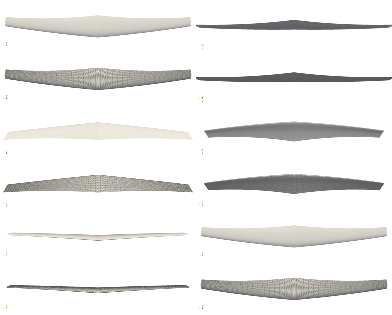
In order to avoid the curving, we reduce the splining degree to only first order—which becomes a linear interpolation—however, the smoothing makes everything just a simple line from root to tip:
spl_k = 1                           # Spline order of distributions along span

# ----------------- GENERATE WING --------------------------------------------------
wing = pnl.gt.generate_loft(airfoil_files, airfoil_path, urfl_NDIVS, lrfl_NDIVS,
                                        semispan, b_low, b_up, b_NDIVS,
                                        chords, twists, x_pos, z_pos;
                                        symmetric=symmetric,
                                        spl_k=spl_k, spl_s=spl_s,
                                        verify_spline=verify_spline
                                    )

# Save vtk and call paraview
pnl.gt.save(wing, file_name; path=save_path, format="vtk")

run(`paraview --data=$(joinpath(save_path, file_name)).vtk`)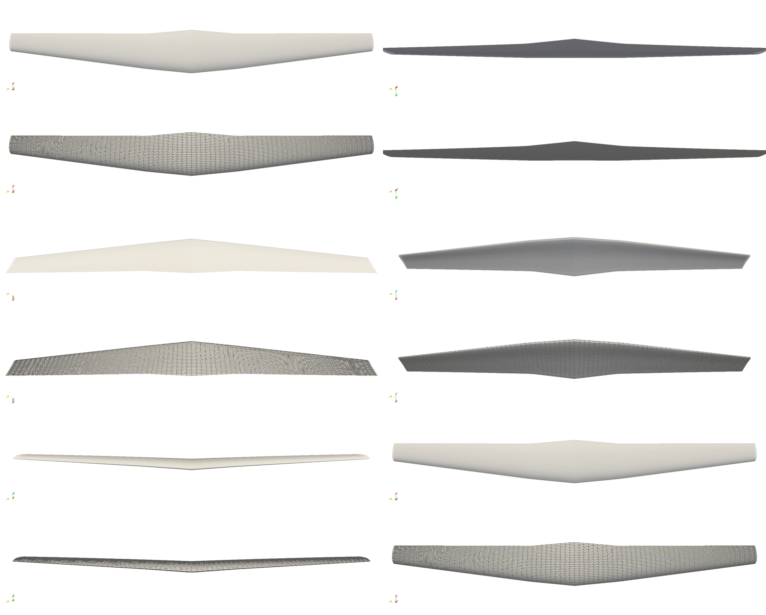
Decreasing the smoothing forces the spline to intersect every data point, finally obtaining the desired geometry:
spl_k = 1                           # Spline order of distributions along span
spl_s = 0.0000001                   # Spline smoothing of distribution along span

# ----------------- GENERATE WING --------------------------------------------------
wing = pnl.gt.generate_loft(airfoil_files, airfoil_path, urfl_NDIVS, lrfl_NDIVS,
                                        semispan, b_low, b_up, b_NDIVS,
                                        chords, twists, x_pos, z_pos;
                                        symmetric=symmetric,
                                        spl_k=spl_k, spl_s=spl_s,
                                        verify_spline=verify_spline
                                    )

# Save vtk and call paraview
pnl.gt.save(wing, file_name; path=save_path, format="vtk")

run(`paraview --data=$(joinpath(save_path, file_name)).vtk`);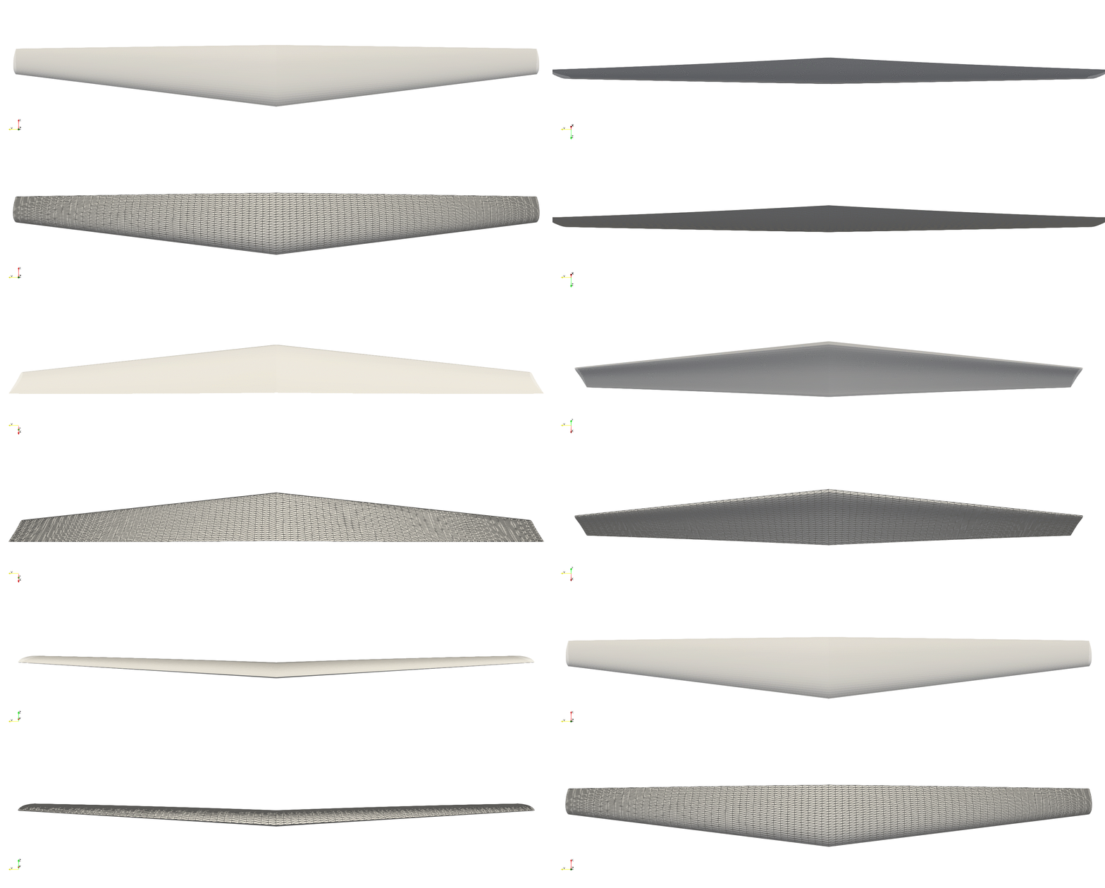
Example — Wing, localized refinement mesh
Here is an example of how to defined a localized refinement. Instead of defining the a uniform discretization around the airfoil cross sections as
urfl_NDIVS = 25                     # Cells on upper side of airfoils
lrfl_NDIVS = 25                     # Cells on lower side of airfoils
we define the divisions as sections of discretization as follows:
urfl_NDIVS = [(0.25, 10,   10.0, false),       # Cells on upper side of airfoils
              (0.50,  7,    1.0, true),
              (0.25,  8, 1/10.0, false)]
lrfl_NDIVS = urfl_NDIVS                        # Cells on lower side of airfoils
The first section starts at the leading edge, with a length of 0.25 and 10 divisions with a geometric expansion of 10.0. The second section is the center of airfoil, and the last one is the trailing edge:
import FLOWPanel as pnl
import GeometricTools as gt
                                # Airfoil data path
airfoil_path = joinpath(pnl.def_data_path, "airfoils");

file_name = "paneledwing02"     # Output file name
save_path = "./"                # Save path

# ----------------- GEOMETRY DESCRIPTION -------------------------------------------
semispan = 10                       # (m) semi-span length

chords = [0.00 0.25;                # (semi-span position, chord c/semib)
          0.25 0.20;
          1.00 0.10]

twists = [0.0 5;                    # (semi-span position, twist (deg))
          1.0 0]

x_pos = [0.00 0;                    # (semi-span position, LE x-position x/semib)
         0.25 1/40;
         1.00 1/8;]

z_pos = [0.00 0;                    # (semi-span position, LE x-position x/semib)
         0.25 1/100;
         1.00 1/50]


airfoil_files = [(0.0, "naca6412.dat"), # (semi-span position, airfoil file)
                 (1.0, "naca6412.dat")]


# ----------------- MESHING PARAMETERS ---------------------------------------------
urfl_NDIVS = [(0.25, 10,   10.0, false),       # Cells on upper side of airfoils
              (0.50,  7,    1.0, true),
              (0.25,  8, 1/10.0, false)]
lrfl_NDIVS = urfl_NDIVS             # Cells on lower side of airfoils
b_NDIVS = 76                        # Span cells


# ----------------- LOFTING PARAMETERS ---------------------------------------------
b_low = -1.0                        # Lower bound of span lofting
b_up = 1.0                          # Upper bound of span lofting
symmetric = true                    # Lofting symmetric about b=0
spl_k = 1                           # Spline order of distributions along span
spl_s = 0.0000001                   # Spline smoothing of distribution along span
verify_spline = false               # Plots the splined distributions
verify_rflspline = true             # Plots the splined airfoil cross sections


# ----------------- GENERATE WING --------------------------------------------------
wing = pnl.gt.generate_loft(airfoil_files, airfoil_path, urfl_NDIVS, lrfl_NDIVS,
                                        semispan, b_low, b_up, b_NDIVS,
                                        chords, twists, x_pos, z_pos;
                                        symmetric=symmetric,
                                        spl_k=spl_k, spl_s=spl_s,
                                        verify_spline=verify_spline,
                                        verify_rflspline=verify_rflspline
                                    )

# Save vtk and call paraview
pnl.gt.save(wing, file_name; path=save_path, format="vtk")

run(`paraview --data=$(joinpath(save_path, file_name)).vtk`)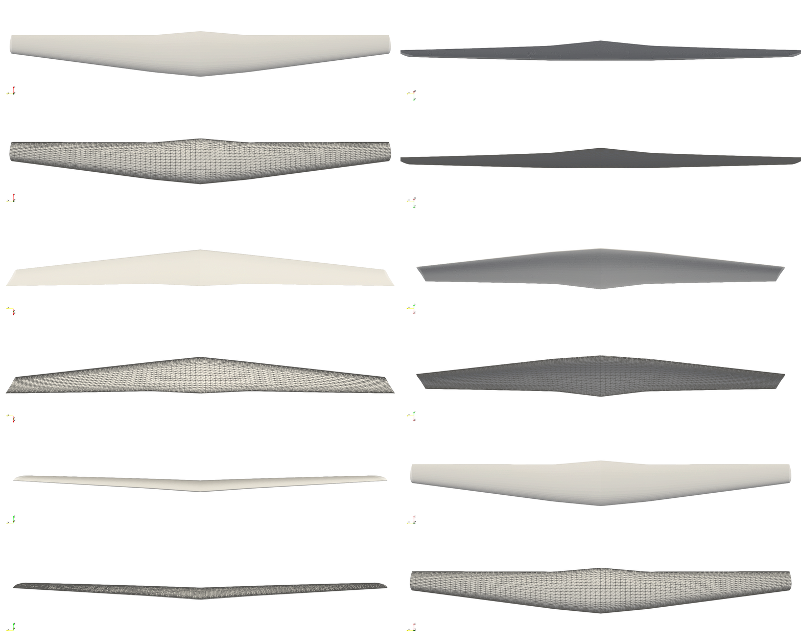
It works great, however, zooming in we realize that the leading edge of the wing is blunt, in spite of refinement. This is due to the splining of the airfoil cross sections smoothing out the high curvature at the leading edge (see below, top image) and failing to actually reconnect bottom and top surfaces. We fix this by decreasing the smoothness of the airfoil splines (see below, bottom image).
rflspl_s = 0.00000001               # Spline smoothing of airfoil cross sections.

# ----------------- GENERATE WING --------------------------------------------------
wing = pnl.gt.generate_loft(airfoil_files, airfoil_path, urfl_NDIVS, lrfl_NDIVS,
                                        semispan, b_low, b_up, b_NDIVS,
                                        chords, twists, x_pos, z_pos;
                                        symmetric=symmetric,
                                        spl_k=spl_k, spl_s=spl_s,
                                        verify_spline=verify_spline,
                                        verify_rflspline=verify_rflspline,
                                        rflspl_s=rflspl_s
                                    )

# Save vtk and call paraview
pnl.gt.save(wing, file_name; path=save_path, format="vtk")

run(`paraview --data=$(joinpath(save_path, file_name)).vtk`)
Finally, we can also refine the mesh towards both tips as shown below.
b_NDIVS = [(1.0, 49, 20.0, true)]   # Span cell sections

# ----------------- GENERATE WING --------------------------------------------------
wing = pnl.gt.generate_loft(airfoil_files, airfoil_path, urfl_NDIVS, lrfl_NDIVS,
                                        semispan, b_low, b_up, b_NDIVS,
                                        chords, twists, x_pos, z_pos;
                                        symmetric=symmetric,
                                        spl_k=spl_k, spl_s=spl_s,
                                        verify_spline=verify_spline,
                                        verify_rflspline=false,
                                        rflspl_s=rflspl_s
                                    )

# Save vtk and call paraview
pnl.gt.save(wing, file_name; path=save_path, format="vtk")

run(`paraview --data=$(joinpath(save_path, file_name)).vtk`)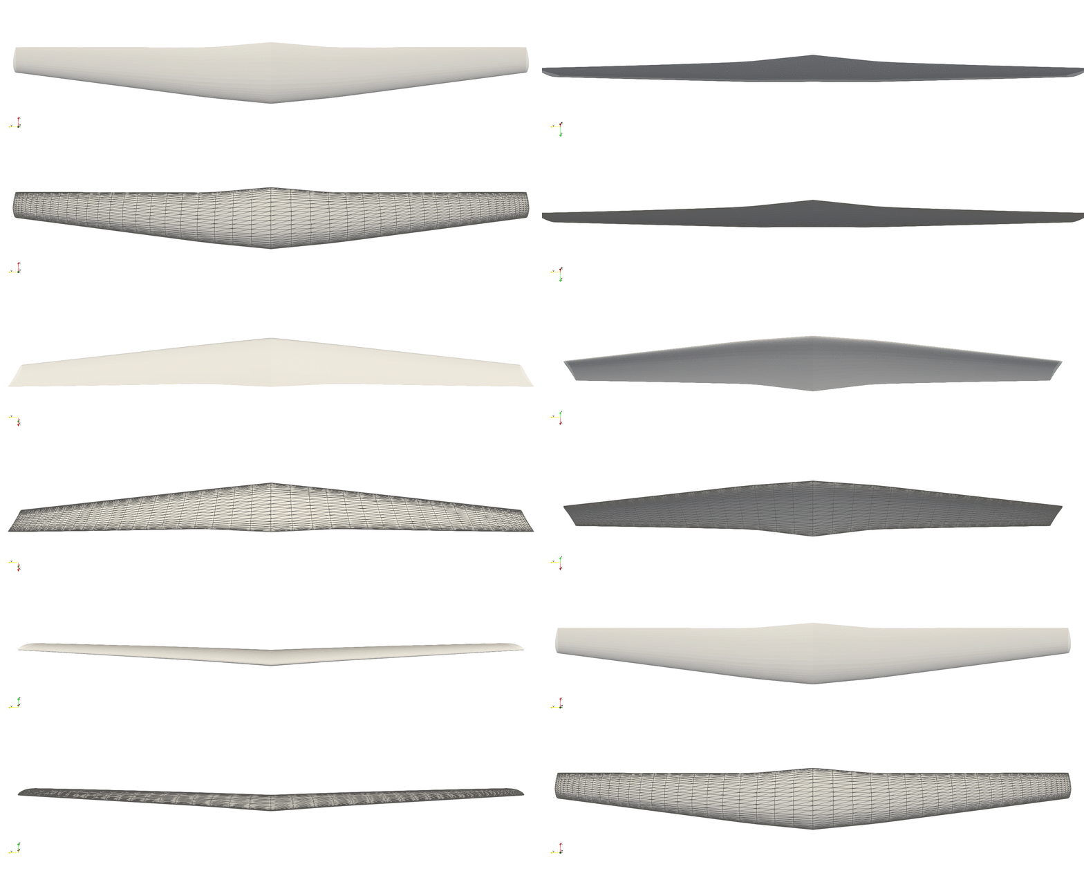
Example — Propeller, nonsymmetric loft
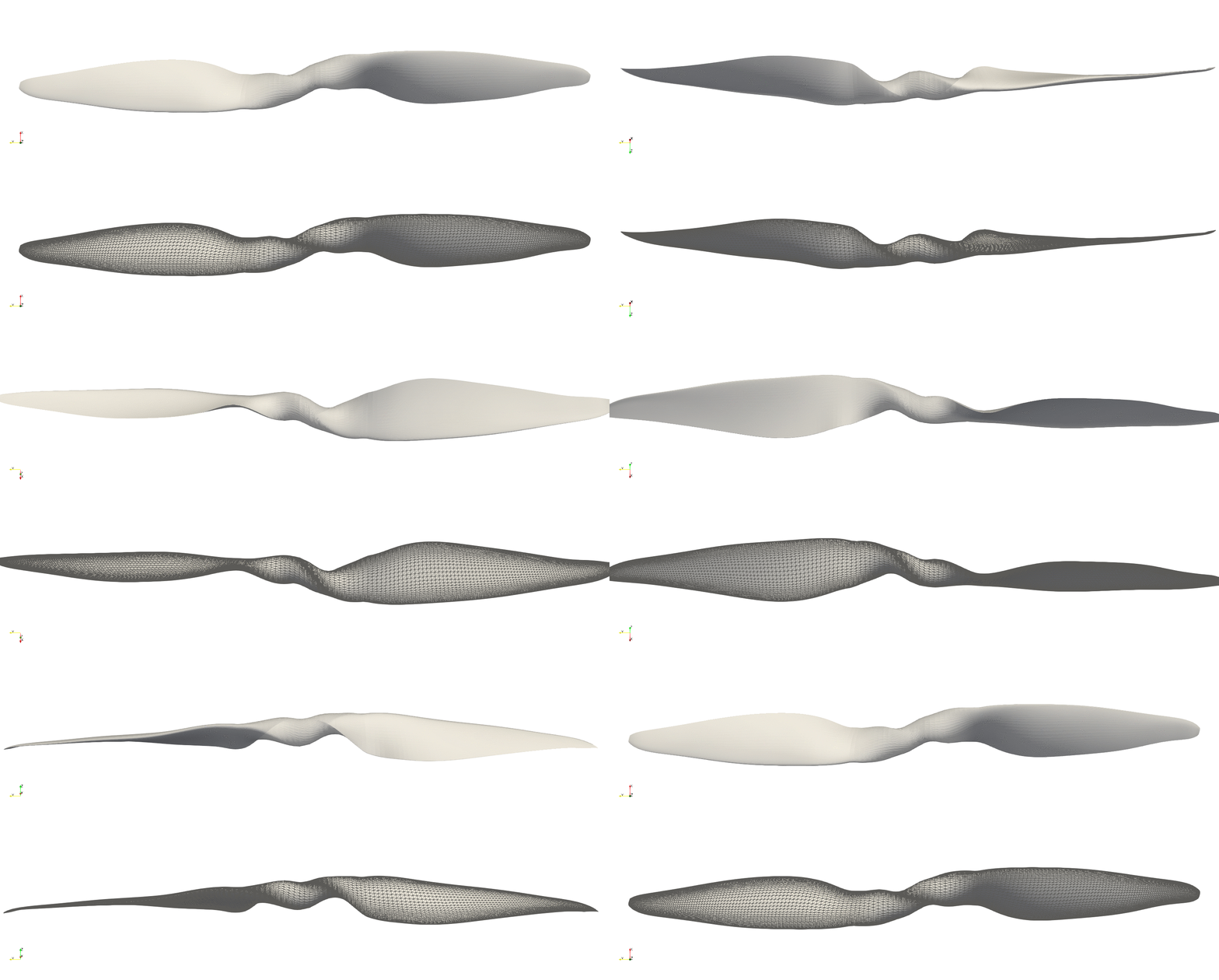
Here we examplify the versatility of the lofting capabilities of our geometric engine by generating a two-bladed rotor that is lofted from tip to tip:
import FLOWPanel as pnl
import GeometricTools as gt
                                # Airfoil data path
airfoil_path = joinpath(pnl.def_data_path, "airfoils");

file_name = "prop00"     # Output file name
save_path = "./"                # Save path

# ----------------- GEOMETRY DESCRIPTION -------------------------------------------
Rtip = 10*0.0254/2                   # (m) Radius of propeller

chords = [0.0 0.134*2/3;                # (blade position, chord c/Rtip)
#             0.086 0.137106*5/6;
#             0.86 0.141*2/3;
#             0.16 0.144606;
            0.2 0.154291;
            0.25 0.175;
            0.3 0.19;
            0.35 0.198;
            0.4 0.202;
            0.45 0.2;
            0.5 0.195;
            0.55 0.186;
            0.6 0.174;
            0.65 0.161;
            0.7 0.145;
            0.75 0.129;
            0.8 0.112;
            0.85 0.096;
            0.9 0.081;
            0.9245 0.071125;
            0.954 0.066125;
            1.0 0.0233333]

twists = [                     # (blade position, twist (deg))
#             0.01 0;
#             0.04715 22.0;
#             0.088145 30.0;
#             0.15 37.86;
#             0.2 45.82;
            0.25 44.19;
            0.3 38.35;
            0.35 33.64;
            0.4 29.9;
            0.45 27.02;
            0.5 24.67;
            0.55 22.62;
            0.6 20.88;
            0.65 19.36;
            0.7 17.98;
            0.75 16.74;
            0.8 15.79;
            0.85 14.64;
            0.9 13.86;
            0.95 12.72;
            1.0 11.53]

x_pos = [                        # (blade position, LE x-position x/Rtip)
#             0.0 0.0;
#             0.0266906 -0.0675531*0;
#             0.0993744 -0.0781078*0;
            0.16992 -0.0810668;
            0.209422 -0.0860351;
            0.260681 -0.0914966;
            0.310887 -0.0958101;
            0.352557 -0.0986618;
            0.39209 -0.101424;
            0.430601 -0.100831;
            0.473388 -0.100419;
            0.521551 -0.0980235;
            0.574004 -0.0947046;
            0.632903 -0.0894484;
            0.69823 -0.083358;
            0.7518 -0.0767745;
            0.801094 -0.0700117;
            0.865384 -0.0616702;
            0.94041 -0.0504677;
            0.973671 -0.0430323;
            0.986802 -0.030395]

z_pos = [0.0 0.0;                  # (blade position, LE x-position x/Rtip)
#             0.075 -0.003*0;
            0.12 0.016;
            0.2 0.044;
            0.4 0.024;
            0.6 0.00278494;
            0.8 -0.02;
            0.95 -0.0388821;
            1.0 -0.056]


airfoil_files = [                    # (blade position, airfoil file)
            (0.0, "Cyl2.csv"),
            (0.02, "Cyl2.csv"),
#             (0.075, "rflsec7.csv"),
#             (0.12, "rflsec6.csv"),
            (0.2, "naca5521.csv"),
            (0.3, "naca4515.csv"),
            (0.4, "naca5513.csv"),
            (0.5, "naca5513.csv"),
            (0.6, "naca4512.csv"),
            (0.7, "naca4511.csv"),
            (0.8, "naca4410.csv"),
            (0.9, "naca4309.csv"),
            (1.0, "naca4309.csv")
                ]

# Mirrors distribution for opposite blade
auxM = [chords[i,j] for i in size(chords,1):-1:1, j in 1:2]
chords = vcat(auxM.*[[-1, 1][j] for i in 1:size(auxM,1), j in 1:2], chords)

auxM = [twists[i,j] for i in size(twists,1):-1:1, j in 1:2]
auxM[:,2] .+= 180
twists = vcat(auxM.*[[-1, -1][j] for i in 1:size(auxM,1), j in 1:2], twists)

auxM = [x_pos[i,j] for i in size(x_pos,1):-1:1, j in 1:2]
x_pos = vcat(auxM.*[[-1, -1][j] for i in 1:size(auxM,1), j in 1:2], x_pos)

auxM = [z_pos[i,j] for i in size(z_pos,1):-1:1, j in 1:2]
z_pos = vcat(auxM.*[[-1, 1][j] for i in 1:size(auxM,1), j in 1:2], z_pos)

# auxM = reverse([(-pos, afile) for (pos, afile) in airfoil_files])
# airfoil_files = vcat(auxM, airfoil_files)

# Some parameters regarding the format of the airfoil files
header_len = 0
delim = ","

# Reads and reflect the airfoils of opposite blade
airfoils = [(pos, pnl.gt.readcontour(f_name; path=airfoil_path,
                                      header_len=header_len, delim=delim,
                                      output="matrix"))
                              for (pos, f_name) in airfoil_files]

auxM = [(-pos, M .* [[1, -1][j] for i in 1:size(M,1), j in 1:2]) for (pos, M) in airfoils]
airfoils = vcat(reverse(auxM), airfoils)


# ----------------- MESHING PARAMETERS ---------------------------------------------
N=4                                         # Scaling of number of cells
urfl_NDIVS = [(0.10, 3*N, 5.0, false),      # Cells on upper side of airfoils
              (0.30, 3*N, 2.0, true),
              (0.10, 3*N, 1/5, false)]
lrfl_NDIVS = urfl_NDIVS                     # Cells on lower side of airfoils
b_NDIVS = [(1.0, 50*N, 5.0, true)]          # Span cells


# ----------------- LOFTING PARAMETERS ---------------------------------------------
b_low = -1.0                        # Lower bound of span lofting
b_up = 1.0                          # Upper bound of span lofting
symmetric = false                   # Lofting symmetric about b=0
spl_k = 5                           # Spline order of distributions along span
spl_s = 0.0001                      # Spline smoothing of distribution along span
rflspl_s = 0.00001                  # Spline smoothing of airfoil cross sections.
verify_spline = true                # Plots the splined distributions
verify_rflspline = true             # Plots the splined airfoil cross sections


# ----------------- GENERATE WING --------------------------------------------------
wing = pnl.gt.generate_loft(airfoils, urfl_NDIVS, lrfl_NDIVS,
                                        Rtip, b_low, b_up, b_NDIVS,
                                        chords, twists, x_pos, z_pos;
                                        symmetric=symmetric,
                                        spl_k=spl_k, spl_s=spl_s,
                                        rflspl_s=rflspl_s,
                                        verify_spline=verify_spline,
                                        verify_rflspline=verify_rflspline
                                    )

# Save vtk and call paraview
pnl.gt.save(wing, file_name; path=save_path, format="vtk")

run(`paraview --data=$(joinpath(save_path, file_name)).vtk`)